Rear Bumper and Gas Tank Skid Plate Install for a Discovery Series I
Introduction
The following outlines the install of the AedoFab Rear Bumper and Gas Tank Skid Plate for a Discovery Series I. This install guide includes the optional rear lights and sway-bar mount extensions.
The rear bumper comes with the following:
- The bumper itself
- Side support brackets
- Fender support corner braces
- All required nuts and bolts
- Gas Tank Skid plate
- Optional replacement tail-lights
- Optional sway bar extensions to push the sway bar beyond the skid plate
Please excuse the dirty bumper! This install guide was written using a customer’s truck and one of the first Discovery bumpers we produced. It has seen a couple years of hard abuse, as you can tell by where the paint has been scratched off. However, a testimonial is that the bumper was easily removed and re-installed for our photo session. The bumper has not suffered any damage in terms of dents or bends. It is still in the same shape as the day it was delivered.
Also, since the truck already had a bumper installed and we just removed it to write this installation guide, some steps show the work completed without before and after pictures. If you are confused or have any questions, don’t hesitate to call.
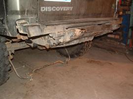
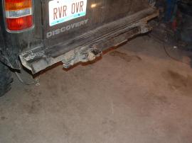
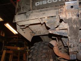
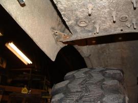
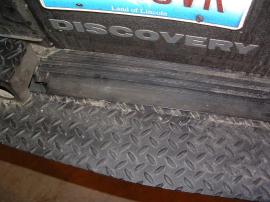
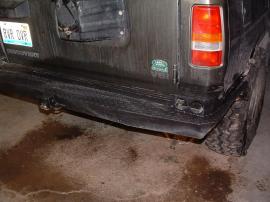
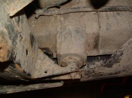
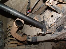
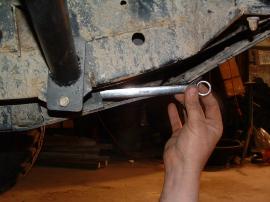
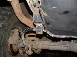
InstallationStep 1 The first step consists of un-bolting and removing your stock components. Disconnect the wire harness from the rear bumper lights and unbolt and remove the rear bumper. Also, remove the trailer tie down rings and disconnect the sway bar from the frame. Finally, remove the mud flaps. The pictures below show the rear bumper and sway bar removed.
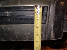
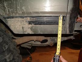
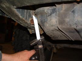
Step 2 Now that the bumper has been removed, it is time to cut away the lower portion of the fenders to make room for the bumper. The pictures show the finished result. Mark the fender about 4 3/4″ inches measuring from the top of the rubber body moulding strip. Cut the body using a cutoff wheel or other power tool if you have one available that can cut aluminum. You can also cut the body with a simple pair of tin-snips if you have nothing else available.
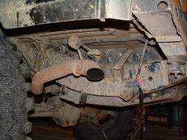
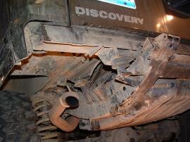
Step 3 Next, you will need to cut the rear exhaust resonator and some pipe away from the exhaust system. Use whatever cutting tool you have available that is up to the job. Even a simple hack-saw will do the trick. You should either purchase an exhaust turn-down or have your local exhaust shop put one on for you. Ideally, turn the exhaust down on an angle. This minimizes the chance of kicking up extra dust on the trail and annoying the folks behind you.
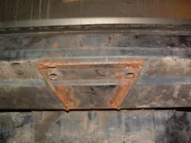
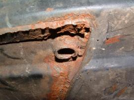
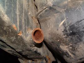
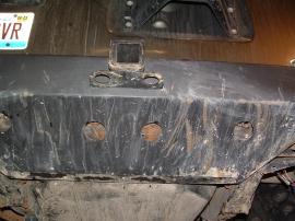
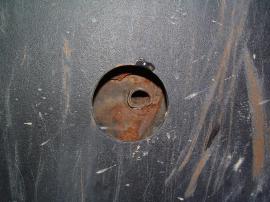
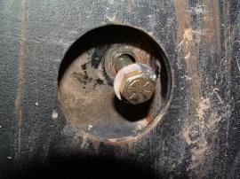
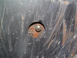
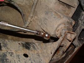
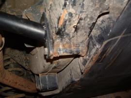
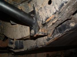
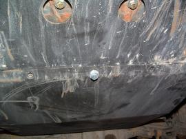
Step 4 The final modification you have to make is to remove the stock trailer hitch. The ideal tool to use is a Saws All. Be sure to cut away from the gas tank no matter what approach you take, as it is plastic and can easily be punctured. Be sure not to cut the small 1/2″ tubes that are present protruding down from the center of the frame under the stock trailer hitch as shown in the pictures. They are used later for mounting of the new bumper.
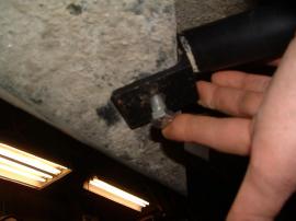
Step 5 A corner brace must be installed to stabilize the fender now that some has been removed. The pictures below show the corner installed. To install the brace, line it up on the fender along the mounting point for the mud flap. It should line up with an existing hole from the mud flap. Use the self-tapping screws and screw into the body. They are short enough so they will not protrude through the side molding on the body. Secure the other part of the brace to the mount with the 1/4″ bolt provided. 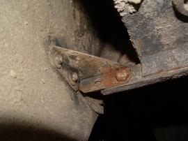
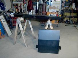
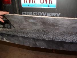
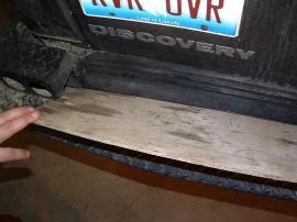
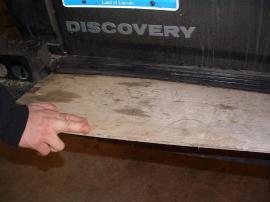
Step 6 This step may need some assistance from a helper, as it entails lifting the rear bumper and placing it onto the rear cross member and under the rubber trim. The difficult part is getting the bumper seated underneath the rubber trim. The easiest approach is to utilize a sheet of 1/4″ plywood cut to about 52 inches. Slide the bumper up to the trim until there is just enough room to slide the plywood under the trim. Use the plywood as a lever to lift up the trim and slide the bumper forward and pull out the plywood.
Step 7Look underneath the bumper and you will see that it has four holes drilled which line up with existing holes in the cross member. The next step is to begin to bolt the bumper onto the body, beginning with these four locations. The bumper is already threaded to accept the four 3/8″ long bolts (and washers). Apply Lock-Tite to the bolts, but only tighten them a bit more than finger-tight, as the bumper may still need to be shifted while the rest of the bolts are installed.
Step 8 The next step is to bolt the bumper to stock mounting holes. As you recall from removing the stock bumper, these bolts go from underneath the truck and towards the back. Utilize the 1/2″ bolts with the large washers. Again, use Lock-Tite and only tighten them slightly, as the bumper may need to be shifted during later steps.
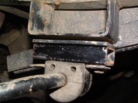
Step 9 Attach the side support brackets to the rear bumper and the frame.Your braces may differ from the picture. You will use the short 7/16″ bolts with 2 washers (on bolt side and nut side) to mount the bracket to the bumper. Use the long bolts to rest the bracket to the frame. However, don’t slide the bolt all the way through, as you will need to wait until you attach the skid plate.
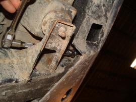
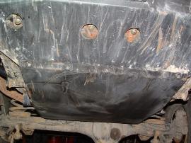
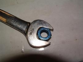
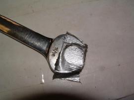
Step 10 Slide the skid plate up against the frame. The skid plate mounts will line up with the sway bar mounts, the existing holes that were used for the trailer tie-down rings, and the threaded holes on the rear bumper. First, finnish pushing the side brace bolts all the way in and through the skid plate side brackets.You may need to slip a washer or two between the skid plate side bracket and the frame to fill some of the space.(every frame is a little different).Using tape to hold the nut onto the wrench as shown will make securing that bolt easier. Then, bolt the swaybar up using the longer 3/8 bolts provided.(picture shows optional swaybar mount extension) Lastly, bolt the skid plate into the rear bumper using the 3/8×1 bolts with a washer. Be sure to use Lock-Tite on all bolts.
Step 11 Now you can tighten down all the bolts. Start with the two bolts in the factory bumper mount,then the four 3/8 bolts going up the center, be sure to gradually tighten them one at a time until they all are fully tight,this will keep the bumper flat on the cross member. .
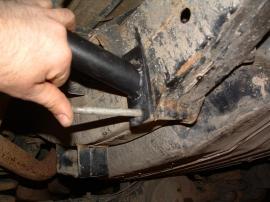
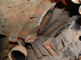
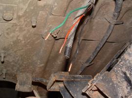
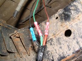
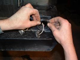
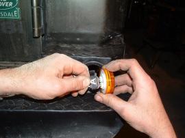
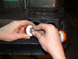
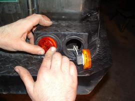
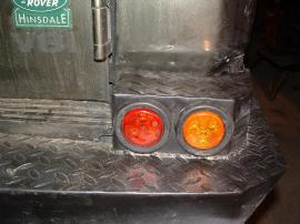
Step 12 The final step is to connect and run the wiring for the LED lights. Cut away the existing light harness as shown. Connect and crimp the new light harness to existing wires,matching the color scheme.(you only use one of the factory black ground wires). Run the wires up through the bumper and out the holes for the lights. Push in the rubber grommets, then connect the wires to the lights (labeled “R” for red, and “A” for amber. Push the lights into the holes.
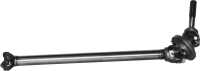
 Quick Disconnects: $65 for two or $125 for a set of four
 To accompany the sway bar disconnects, you may also need a front Sway Bar Extension.
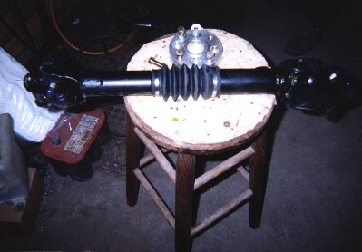
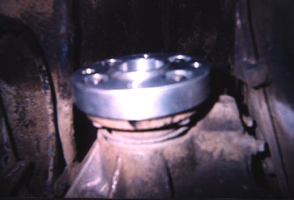
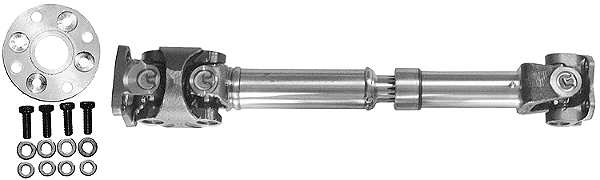
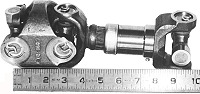
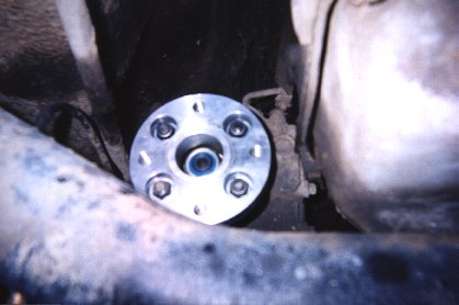 As you can see, the adapter is threaded to accept the supplied bolts. Be sure not to forget the lock-washers.


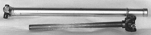
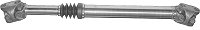
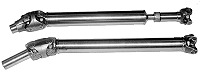
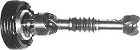
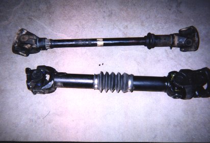
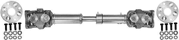 Double Cardon Driveshaft – $389 Including Shipping, Bolts, and Adapter Plate